

| Operation instructions for quality test of brake master cylinder | |||
| NO. | Operation Diagram | Operation Instructions | Requirements |
| 1 |
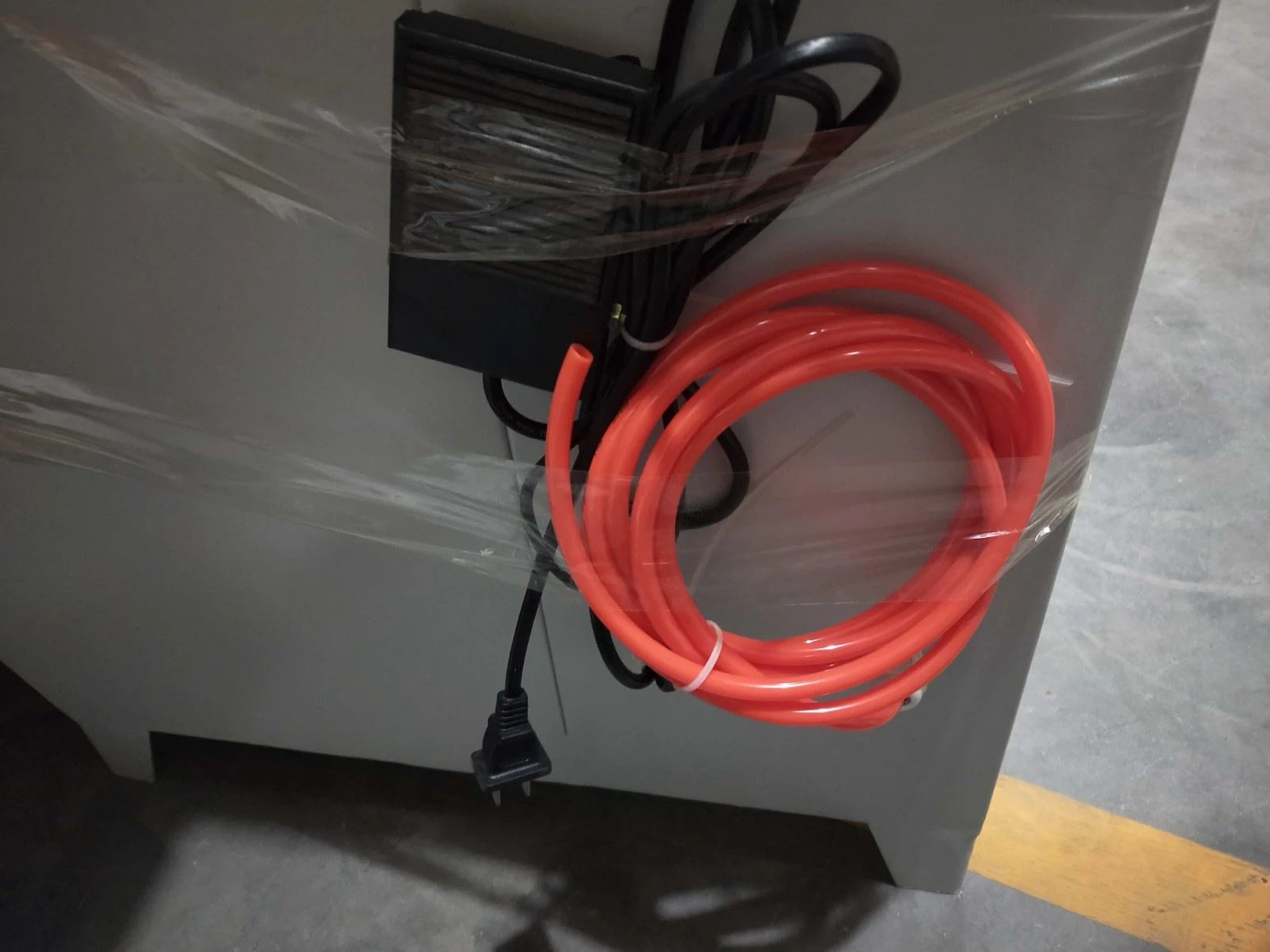
| The red pipe is connected to the air compressor, and the black wire is connected to the power supply (using a voltage converter). | |
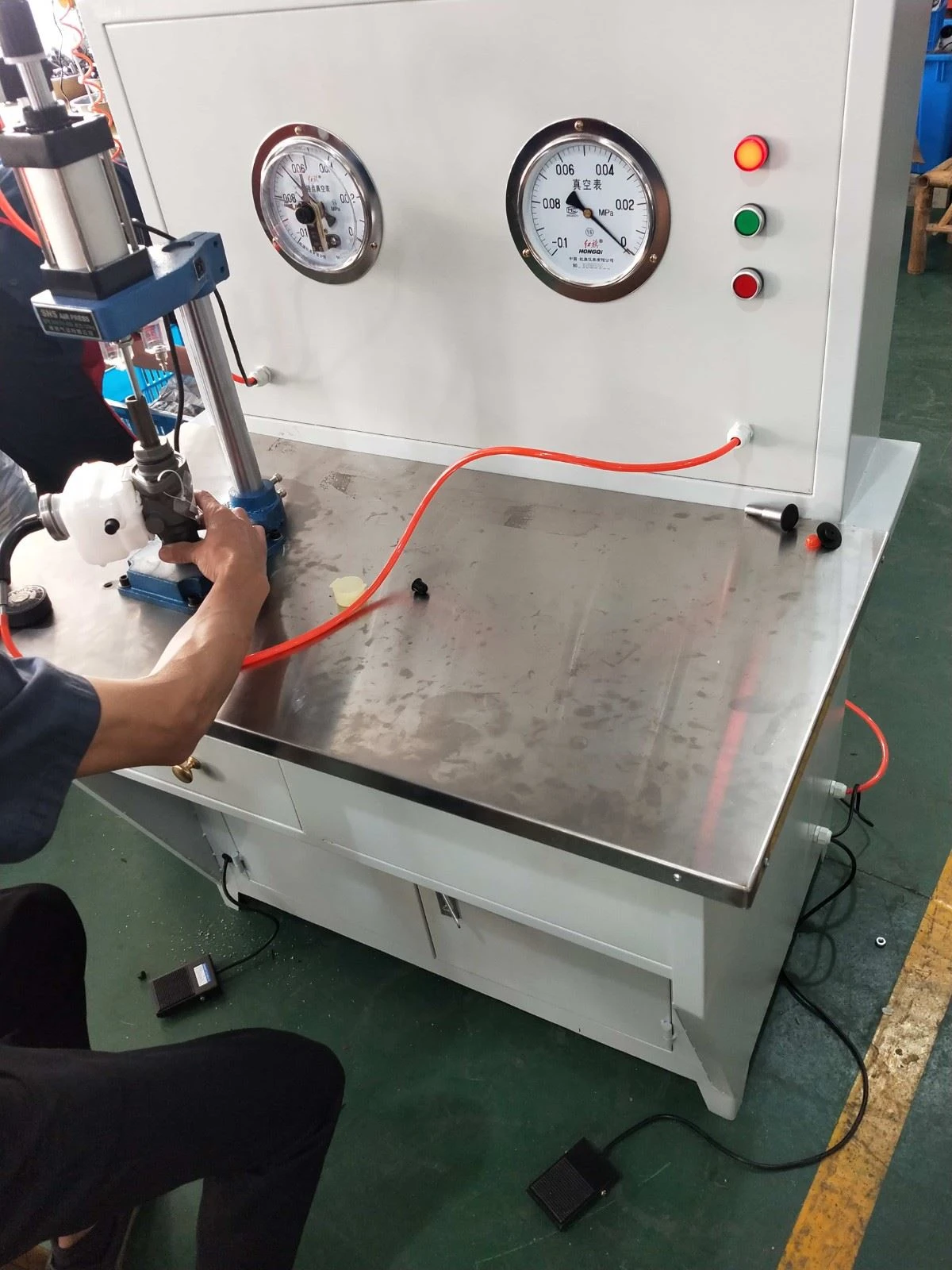
| 2 |
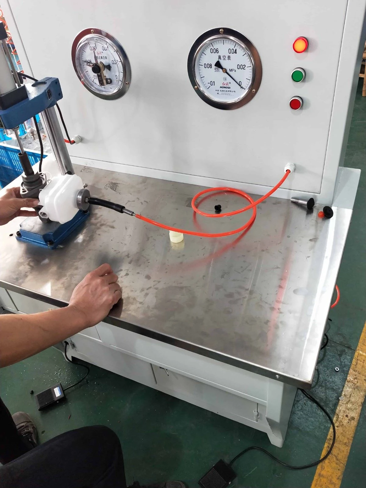
| (1) The green button is on, the red button is off. (2) Press the open button, the red light is on, and the pointer of the "electric contact vacuum gauge" on the left shows 0.08MPa (normal working range 0.05MPa-0.08MPa) (3) The left side is the pushrod control pedal (cylinder control pedal), and the right side is the vacuum control pedal. | The surface of the workbench should be clean and tidy, the materials should be intact, and the instrument response should be normal. Check all of these then we can start to work. |
| 3 |
| Confirm that the oil passage of the reservoir is well sealed. The pipeline of the tester is well connected. | |
| 4 |
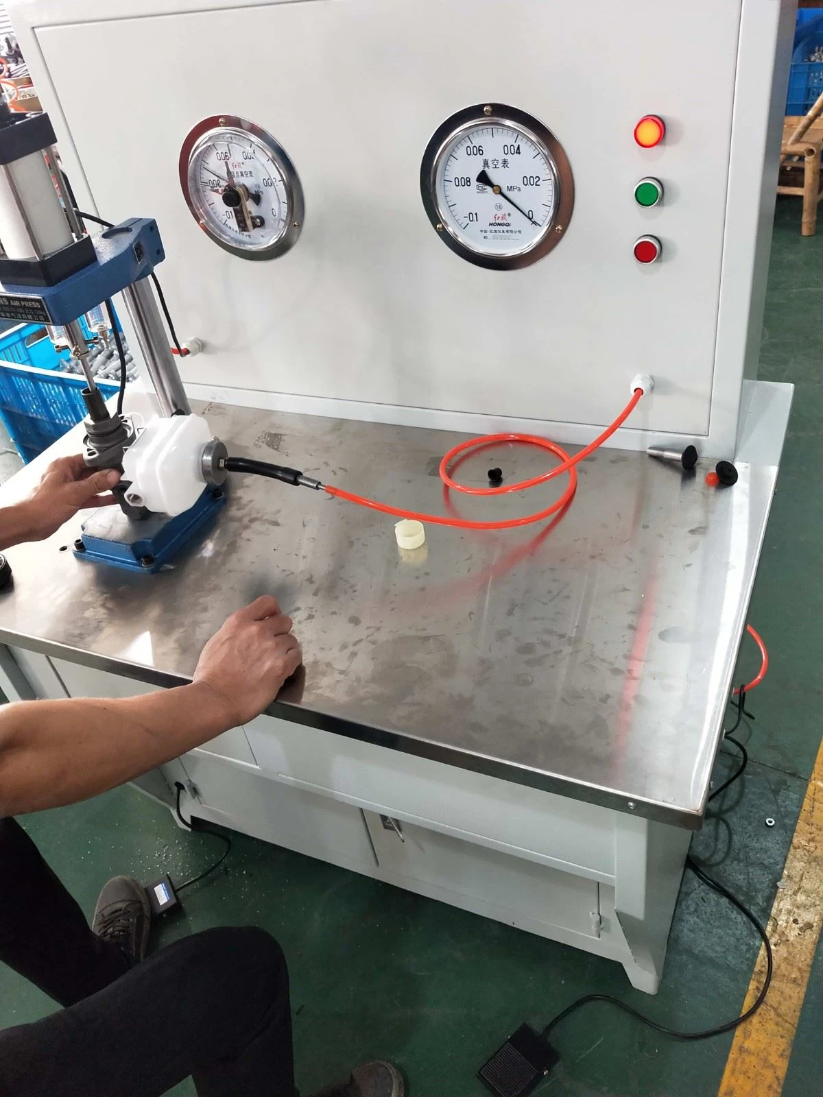
| Place the brake cylinder on the workbench. | The pushrod is aligned with the piston. |
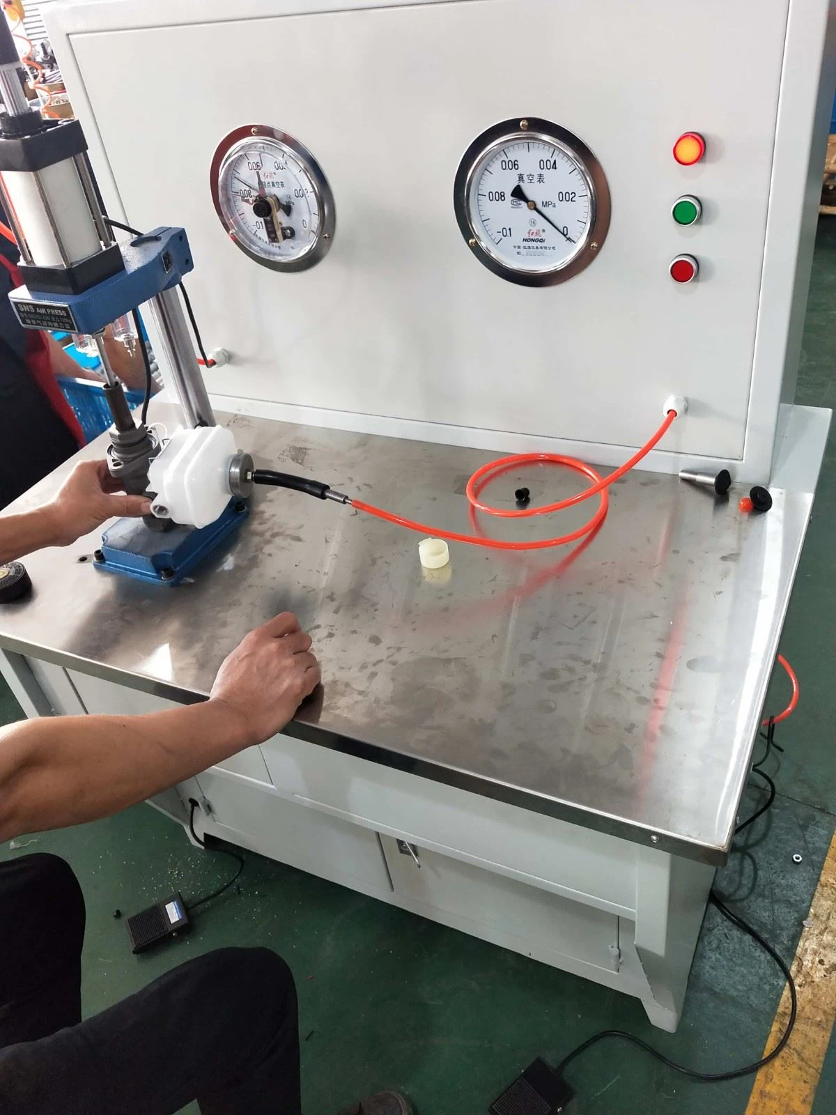
| 5 |
| Step on the pushrod control pedal and the master cylinder starts to work. | |
| 6 |
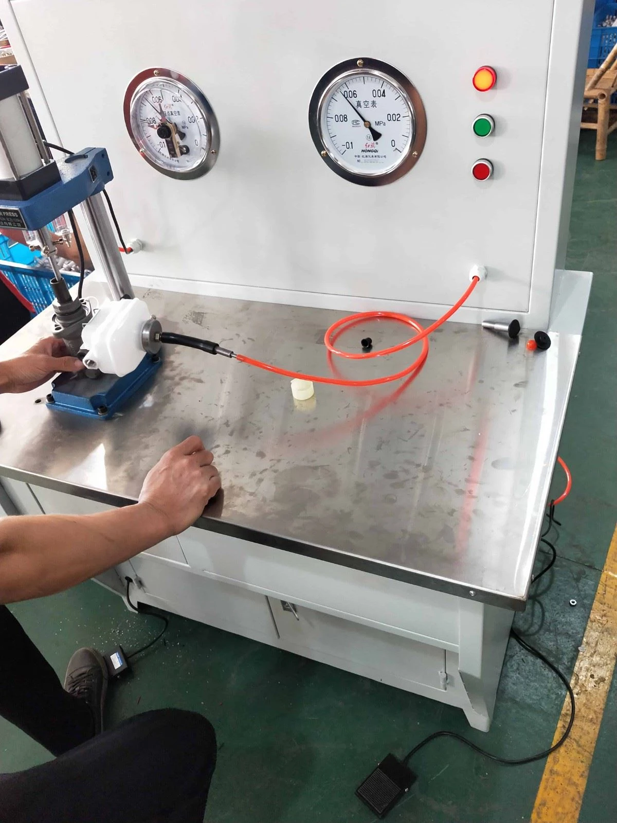
| Step on the vacuum control pedal and observe that the pointer of the vacuum gauge is above 0.05MPa. | |
| 7 |
| Release the vacuum control pedal and observe for 15 seconds, the pointer of the vacuum gauge does not move. | |
| 8 |
| Block the first oil outlet with your fingers, then release the pushrod control pedal, and observe that the pointer of the vacuum gauge returns to 0MPa. | |
| 9 | Repeat steps 5, 6, and 7 again. | ||
| 10 |
| Block the second oil outlet with your fingers, then release the pushrod control pedal, and observe that the pointer of the vacuum gauge returns to 0MPa. | |
| The brake master cylinder passes the above test can be confirmed as qualified. | |||

Knowledge
Operation instructions for quality test of brake master cylinder
Oct 23, 2020
Leave a message



Send Inquiry